Publication
Metrics
AI Quick Summary
This paper presents a high-accuracy calibration technique for PCB coil sensors used in particle accelerator magnet measurements, achieving simultaneous determination of rotation radius and plane offset. The method leverages precise planar wire loops and dynamic, in-situ calibration, validated experimentally with a Coordinate Measuring Machine (CMM).
Paper Preview
Abstract
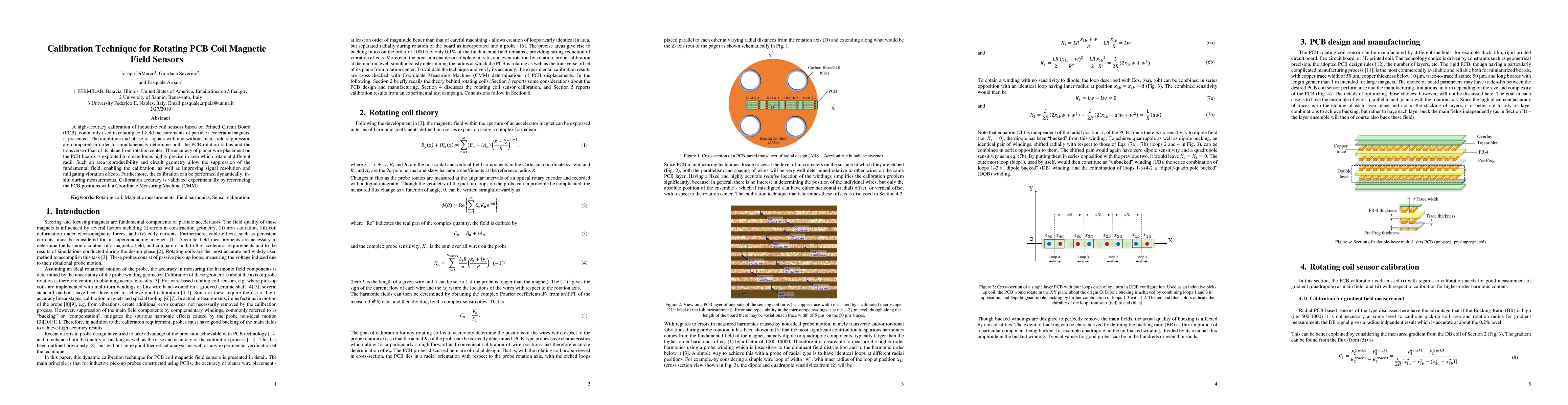
A high-accuracy calibration of inductive coil sensors based on Printed Circuit Board (PCB), commonly used in rotating coil field measurements of particle accelerator magnets, is presented. The amplitude and phase of signals with and without main field suppression are compared in order to simultaneously determine both the PCB rotation radius and the transverse offset of its plane from rotation center. The accuracy of planar wire placement on the PCB boards is exploited to create loops highly precise in area which rotate at different radii. Such an area reproducibility and circuit geometry allow the suppression of the fundamental field, enabling the calibration, as well as improving signal resolution and mitigating vibration effects. Furthermore, the calibration can be performed dynamically, in-situ during measurements. Calibration accuracy is validated experimentally by referencing the PCB positions with a Coordinate Measuring Machine (CMM).
AI Key Findings
Get AI-generated insights about this paper's methodology, results, significance, and more — seven facets brought into focus.
Impact
Paper Details
PDF Preview
Key Terms
Citation Network
Current paper (gray), citations (green), references (blue)
Display is limited for performance on very large graphs.
Discussion 0