Phase Noise in RF and Microwave Amplifiers

Source: ArXiv

AI Quick Summary

This paper examines the two main types of phase noise in RF and microwave amplifiers: white and flicker. It highlights the distinct behaviors of these noise types under various amplifier configurations, showing that flicker noise scales differently depending on whether amplifiers are connected in parallel or cascaded. The study validates a theoretical model explaining the near-dc flicker noise through parametric modulation in semiconductors.

Share: Share on X LinkedIn

Summary

Understanding the amplifier phase noise is a critical issue in numerous fields of engineering and physics, like oscillators, frequency synthesis, telecommunications, radars, spectroscopy, in the emerging domain of microwave photonics, and in more exotic domains like radio astronomy, particle accelerators, etc. 
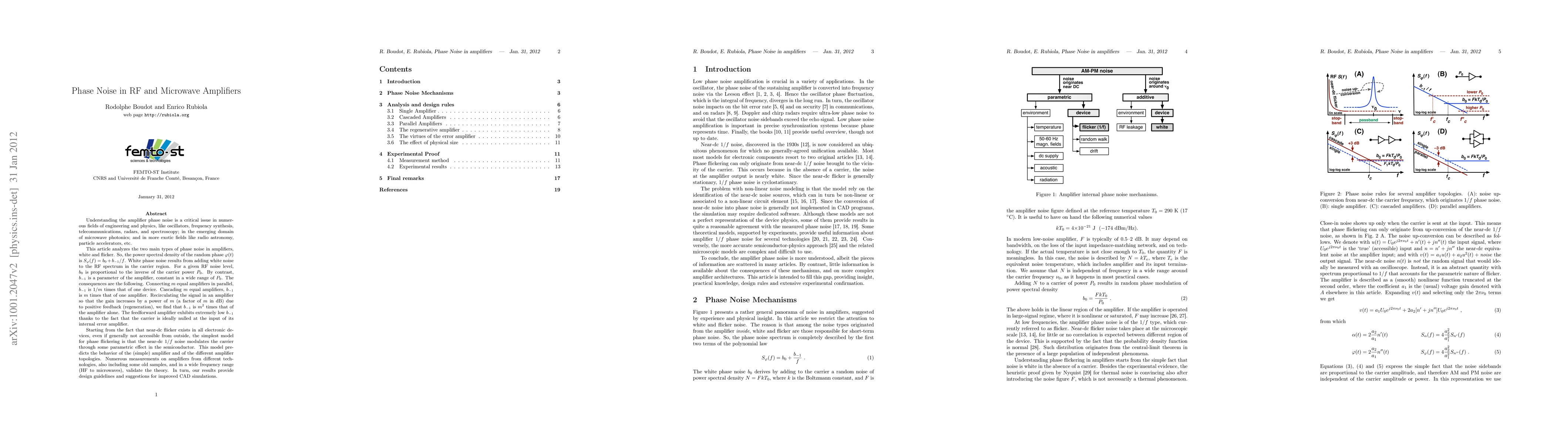
This article analyzes the two main types of phase noise in amplifiers, white and flicker. White phase noise results from adding white noise to the RF spectrum around the carrier. For a given amount of RF noise added, noise is proportional to the inverse of the carrier power. By contrast, the 1/f coefficient is a constant parameter of the amplifier, in a wide range of carrier power. This fact has amazing consequences on different amplifier topologies. Connecting m equal amplifiers in parallel, flicker is 1/m times that of one device. Cascading m equal amplifiers, flicker is m times that of one amplifier. Recirculating the signal in an amplifier so that the gain increases by a power of m (a factor of m in dB) due to positive feedback (regeneration), which for integer m is similar to the case of m amplifiers, we find that flicker is m^2 times that of the amplifier alone. Starting from the fact that near-dc flicker exists in all electronic devices, although generally not accessible from outside, the simplest model for the 1/f phase noise is that the near-dc 1/f noise phase-modulates the carrier through some parametric effect in the semiconductor. This model predicts the behavior of the (simple) amplifier and of the different amplifier topologies. Numerous measurements on amplifiers from different technologies and frequencies (HF to microwaves), also including some obsolete amplifiers, validate the theory.

AI Key Findings

Generated Sep 01, 2025

Methodology

The research analyzes phase noise in RF and microwave amplifiers, focusing on white and flicker noise types. It explores how connecting amplifiers in parallel or cascading them affects phase noise, and validates the theory with measurements on amplifiers from various technologies and frequencies.

Key Results

  • Flicker noise in parallel amplifiers is reduced by a factor of m, or 3log2(m) dB, assuming perfect symmetry and no dissipative losses.
  • Regenerative amplifier gain is given by A = A0 / (1 - A0β), where A0 is the voltage gain of the simple amplifier and β is the gain of the feedback path.
  • The flicker noise in a regenerative amplifier is m^2 times that of a single amplifier.
  • Feedforward amplifier exhibits low phase noise due to an error amplifier processing only the error signal of the power amplifier, which is a small signal.
  • Experimental results confirm the behavioral rules stated in the paper for different amplifier configurations, including single amplifiers, cascaded amplifiers, parallel amplifiers, and regenerative amplifiers.

Significance

This research is crucial for numerous engineering and physics fields, including oscillators, frequency synthesis, telecommunications, radars, spectroscopy, and emerging domains like microwave photonics. Understanding phase noise in amplifiers can lead to improved designs and performance in these areas.

Technical Contribution

The paper presents a comprehensive analysis of phase noise in RF and microwave amplifiers, including theoretical models and experimental validation for various amplifier configurations.

Novelty

The research offers a detailed examination of phase noise in amplifiers, highlighting the effects of different topologies (parallel, cascade, regenerative) and providing experimental evidence supporting the theoretical predictions.

Limitations

  • The inverse-volume law for flicker coefficient might not hold at nanoscale or large scale due to coherence length limitations and loss of independence in elementary volumes.
  • Measurements are limited by the background noise of the measurement system, particularly for SiGe amplifiers with outstandingly low 1/f noise.

Future Work

  • Explore the inverse-volume law's applicability at different scales and refine design guidelines accordingly.
  • Investigate methods to further reduce phase noise in amplifiers, especially for low-power applications.

Paper Details

PDF Preview

Download PDF

Key Terms

carrier (0.272)
carrier (0.257)
noise (0.237)
noise (0.235)
white (0.221)
white (0.214)
rf (0.210)
dc (0.201)

Citation Network

Current paper (gray), citations (green), references (blue)

Display is limited for performance on very large graphs.

Current Paper
Citations
References
Click to view

Similar Papers

Found 4 papers
Title Authors Year Actions

Comments (0)

This website uses cookies to ensure you get the best experience. Learn more