High Precision MultiWave Rectifier Circuit Operating in Low Voltage 1.5 Volt Current Mode
Publication
Metrics
AI Quick Summary
This paper presents a high precision multiwave rectifier circuit operating in low voltage current modes using CMOS technology, achieving high frequency response and low power losses. The circuit employs a combination of current comparator, current mirror, and CMOS inverter circuits, validated by PSpice simulations showing optimal performance up to 200 MHz.
Paper Preview
Abstract
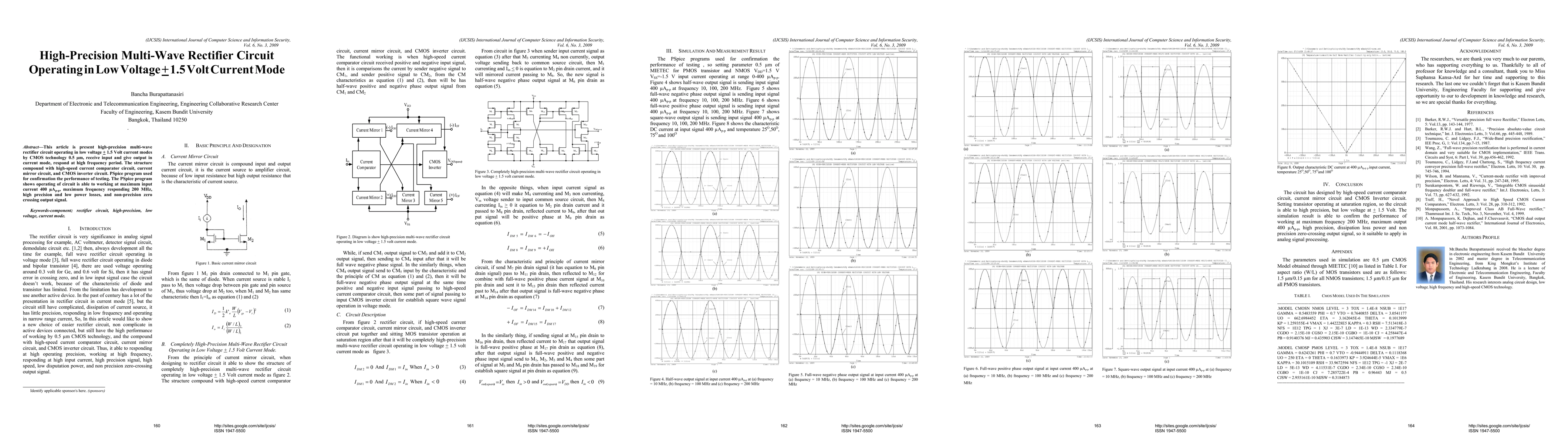
This article is present high precision multiwave rectifier circuit operating in low voltage plus or minus 1.5 Volt current modes by CMOS technology 0.5 \mum, receive input and give output in current mode, respond at high frequency period. The structure compound with high speed current comparator circuit, current mirror circuit, and CMOS inverter circuit. PSpice program used for confirmation the performance of testing. The PSpice program shows operating of circuit is able to working at maximum input current 400 \muAp p, maximum frequency responding 200 MHz, high precision and low power losses, and non-precision zero crossing output signal.
AI Key Findings
Get AI-generated insights about this paper's methodology, results, significance, and more — seven facets brought into focus.
Impact
Paper Details
PDF Preview
Key Terms
Citation Network
Current paper (gray), citations (green), references (blue)
Display is limited for performance on very large graphs.
Discussion 0