Sinusoidal Frequency Doublers Circuit With Low Voltage 1.5 Volt CMOS Inverter
Publication
Metrics
AI Quick Summary
This paper presents a sinusoidal frequency doubler circuit utilizing a low voltage 1.5V CMOS inverter, composed of a CMOS inverter, differential amplifier, and square root circuit, designed for high precision, low error, and low power consumption. Simulation using PSpice confirms the functionality of the MOS transistors in active and saturation periods.
Paper Preview
Abstract
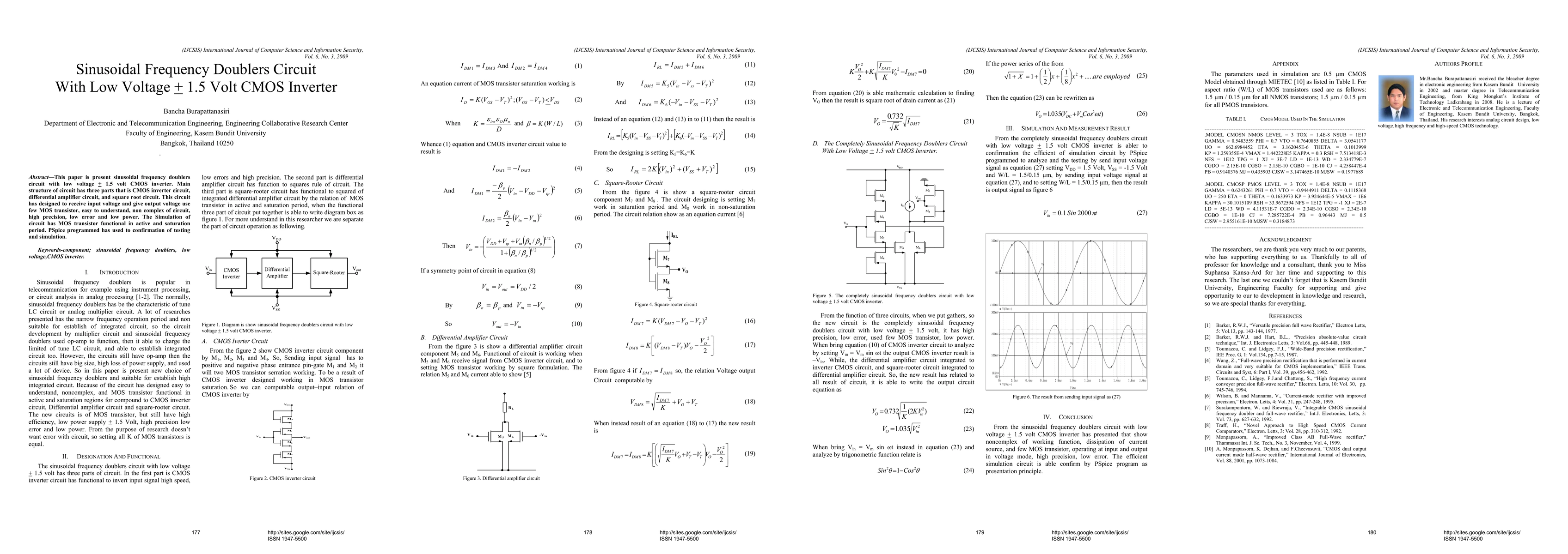
This paper is present sinusoidal frequency doublers circuit with low voltage 1.5 volt CMOS inverter. Main structure of circuit has three parts that is CMOS inverter circuit, differential amplifier circuit, and square root circuit. This circuit has designed to receive input voltage and give output voltage use few MOS transistor, easy to understand, non complex of circuit, high precision, low error and low power. The Simulation of circuit has MOS transistor functional in active and saturation period. PSpice programmed has used to confirmation of testing and simulation.
AI Key Findings — Failed
Key findings generation failed. Failed to start generation process
Impact
Paper Details
PDF Preview
Key Terms
Citation Network
Current paper (gray), citations (green), references (blue)
Display is limited for performance on very large graphs.
Discussion 0